Electric Vehicle Charger Communications Board
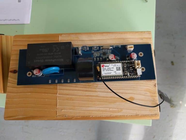
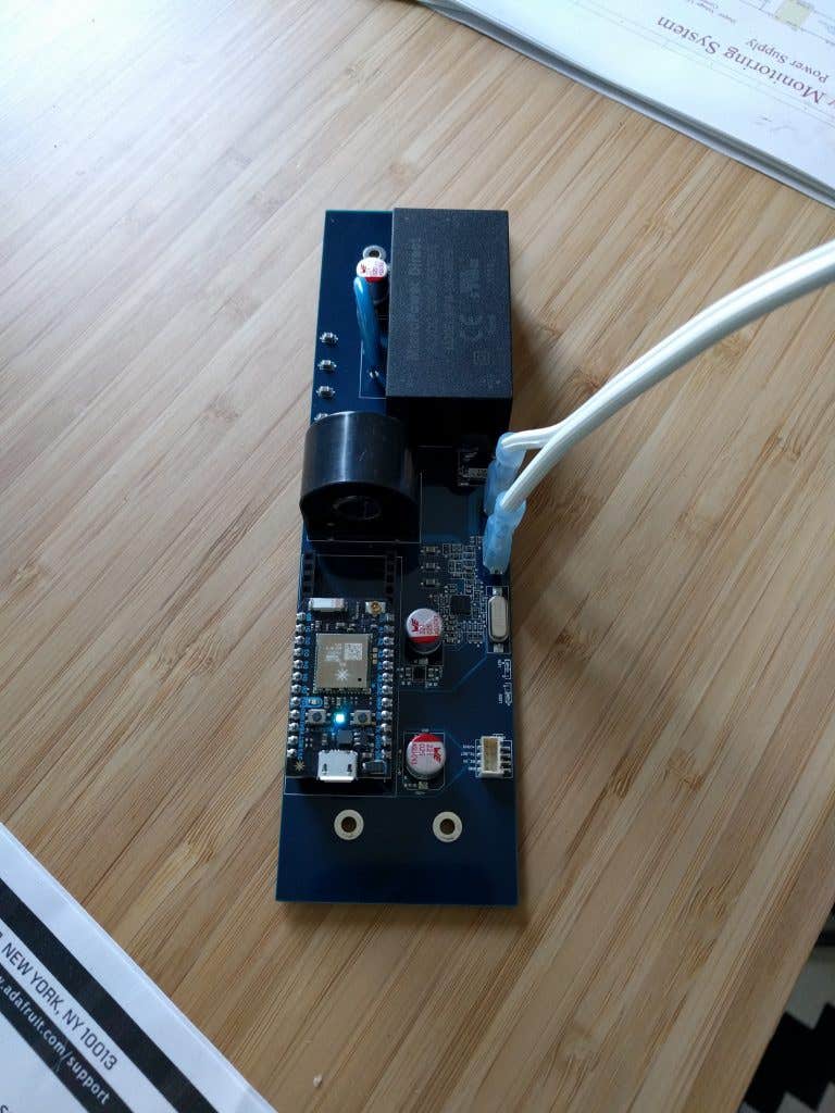
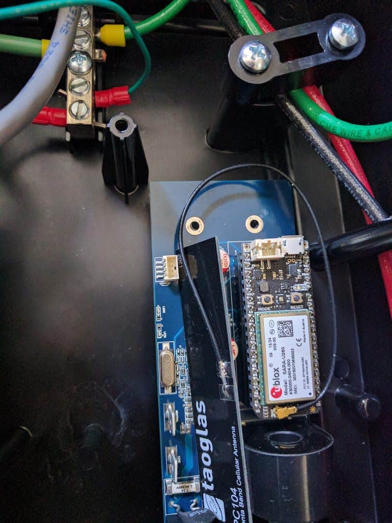
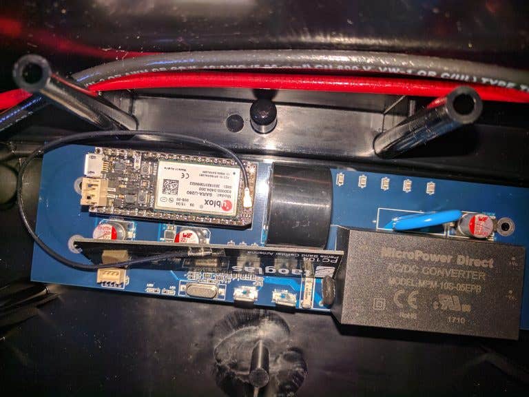
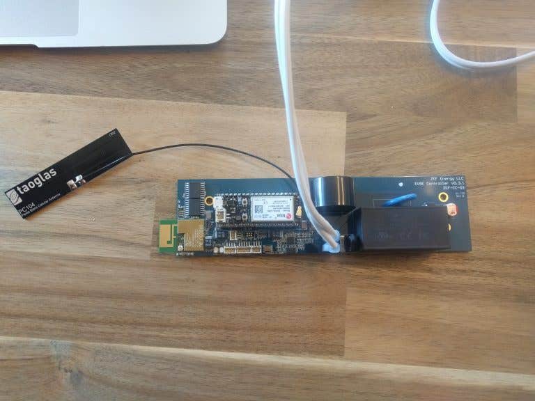
In this project the schematic of a mixed signal circuit was designed consisting of AC/DC Power Supply, DC/DC SMPS Regulator, Power Measuring Chip, Wifi/Bluetooth Board, CT (Current Transformer) and various connectors. The interface between the communications board and the STPM32 Power Measuring Chip was SPI. The PCB was designed taking into account all the requirements and constraints so that the board could be UL certified. I partitioned the schematic so that the power analog and digital components were placed so that the UL certification can be achieved. A second version of the board described above was also designed. For this version optocouplers were integrated for the SPI lines to ensure isolation between AC tabs and the microcontroller pins. Also there was integrated a second communications board that came in SMD format. This board can be seen in the lower left corner in the second version section below. The GPIO capability was extended and special I/O connectors were used an

Su di me
I am an expert Electronics PCB Design Engineer with 10 years industry experience. I can design and implement analog, digital and high speed circuits, FPGA circuits and write firmware in VHDL and Embedded C. I can design rigid, rigid-flex or flex PCBs, also I can do 3D modelling of electronic components. You can find a lot of interesting projects on my site: [login to view URL]